Mechanics of Materials: Free-Body Diagrams (FBDs)
This article was translated from its source language with AI assistance. Please check technical terms and equations against the original.
Hello. Today, we will examine the concept essential to solid mechanics calledFree-Body Diagram(FBD). A free-body diagram (FBD) is essential to static analysis of rigid or deformable bodies. This post will help you understand its importance and how to draw one.
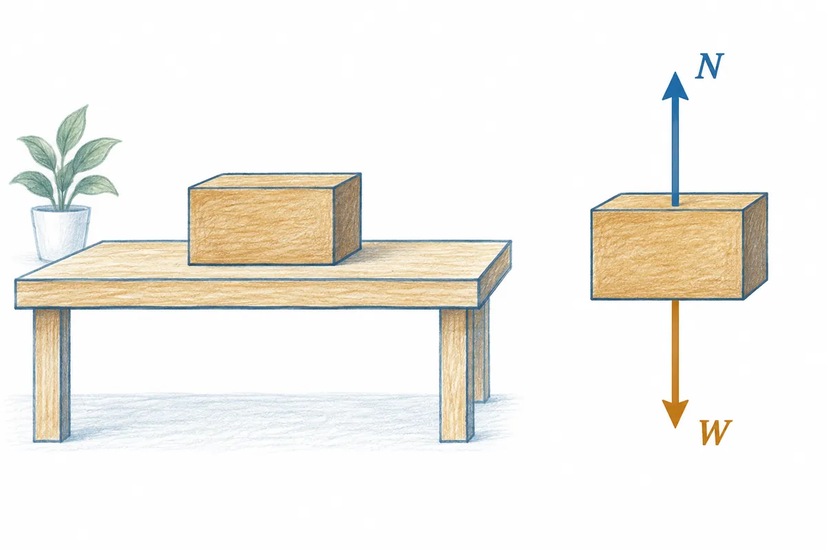
A free-body diagram shows all the forces acting on a body. These include applied forces and moments, reaction forces and moments, and connection forces between individual components. In other words, all these forces must be shown in an FBD to understand the body's equilibrium accurately.
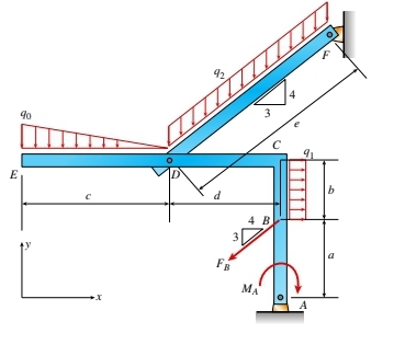
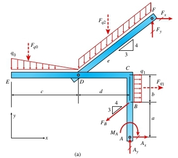
For example, the complete FBD of the planar frame shown in Figure 1 below appears in Figure 2(a). It includes all applied and reaction forces, along with statically equivalent concentrated loads for all distributed loads. To represent distributed loads q0, q1, and q2, statically equivalent forces Fq0, Fq1, and Fq2, acting at the centroid of each distributed load, are used to solve the equilibrium equations.
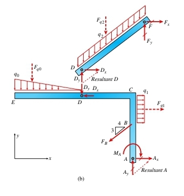
Next, as shown in Figure 2(b), the planar frame can be separated, and an individual FBD drawn for each part. This reveals the pin connection forces (Dx, Dy). Both FBDs must show the reaction forces Ax and Ay at the pin support A, along with all applied forces, including Fx and Fy.
An FBD drawn in this way plays an important role in determining equilibrium. Static sign conventions are generally used to solve for support reactions: forces acting in the positive coordinate directions are assumed positive, and moment vectors are determined using the right-hand rule.
FBDs are tools that help us understand the forces acting on a body visually and analyze the results.
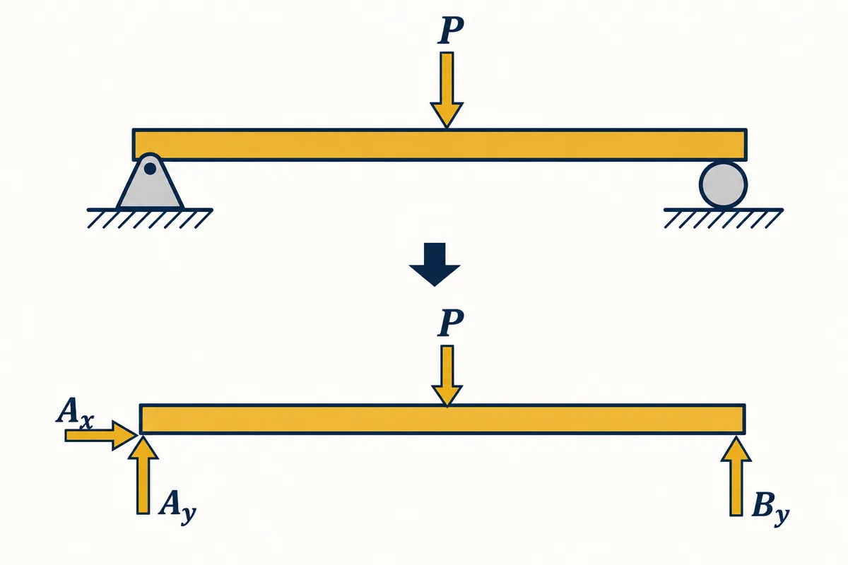
General Procedure for Drawing a Free-Body Diagram
1. First, choose the body you wish to analyze. It may be a single object or part of a system.
2. Isolate the chosen body from its surroundings so that only external forces acting on it are considered. At this stage, identify all external forces and moments connected to the body.
3. Identify every force acting on the body. These may include gravity, friction, and tension. Specify each force's point of application and direction as well.
4. Represent each identified force with an arrow. Its length represents the magnitude, and its direction represents the direction of the force. Place the arrow at the appropriate point of application on the body.
5. If the body is supported or fixed by another body or surface, consider the reaction forces at those points. These are the forces needed to support or fix the body and generally point from the support toward the body.
6. After showing all forces with arrows, label each with an appropriate symbol for its physical meaning. For example, gravity can be shown as W or mg, friction as f, and tension as T.
7. Finally, calculate the vector sum of all forces. If their sum is zero, the body is in a static state.
That concludes this explanation of FBDs. Thank you.
Source: [1] Mechanics of Materials, J. M. Gere, B. J. Goodnoet. al - 2012 - Cengage learning
Original illustrations created to help explain this article.
Original on Tistory ↗