Understanding Stress Concentration: The Effects of Holes and Corners
This article was translated from its source language with AI assistance. Please check technical terms and equations against the original.
Key point: Even with the same average stress, local stress can increase around holes and changes in geometry. Read a stress concentration factor together with the nominal stress used as its denominator and the assumptions concerning geometry, loading, and elasticity.
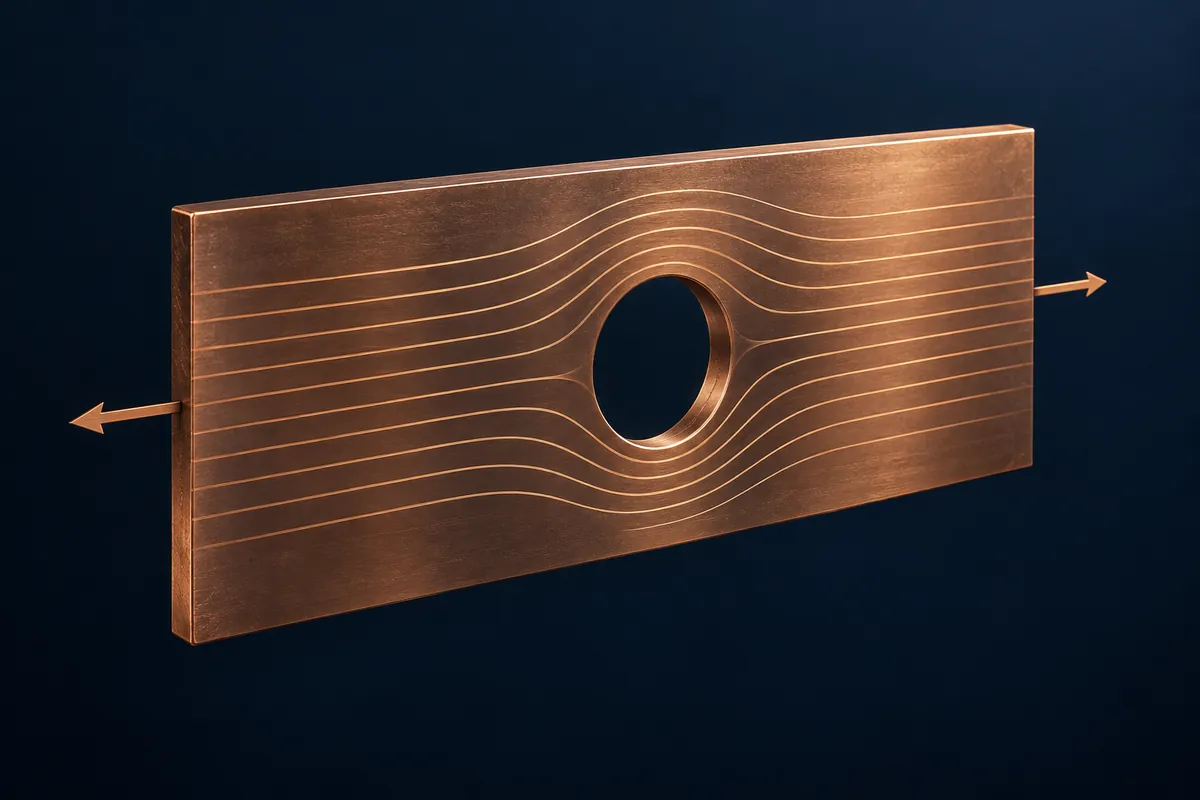
The sequence at a glance
This is an explanatory illustration, not a screenshot or an actual test result.
1. Mark the geometry and loading direction
2. Define the cross section used for nominal stress
3. Check the assumptions and factor
4. Calculate the local value and check the units
5. Check additional conditions needed to assess actual failure
The same force does not produce the same stress everywhere
The same force pulling a plate does not create the same stress at every point in it. A hole or a change in cross section alters the load transfer path, and stress components can vary with location. Nominal stress, calculated by dividing force by cross-sectional area, is a starting point for comparison, but it does not represent the maximum within a small local region. When examining a component, identify both the overall section and its local geometry.
This article explains idealized examples in linear elastic mechanics of materials. It does not report an assessment of an actual component's safety, yield behavior, fatigue life, or failure load. A visible hole does not justify always multiplying by the same factor or declaring the component dangerous. First organize the geometry, loading direction, and boundary conditions, then find a solution or reference applicable to them.
| Term | What it represents | Conditions needed to interpret it |
| Load P | Force transmitted to the component | Magnitude, direction, distribution, and units |
| Nominal stress | Stress calculated using a selected section and reference | Whether the gross or net section is used |
| Local stress | Stress at a particular location, such as a hole or corner | Component, location, loading, and boundary conditions |
| Elastic stress concentration factor Kt | Maximum local stress / defined nominal stress | A reference with matching geometry and denominator definition |
| Hole diameter d / plate width W | Geometric ratio used to compare finite-width effects | Measurement conventions for d and W |
| Yield and fatigue assessment | A separate assessment based on the material and load history | Information beyond one local value is needed |
Read the load path around a hole through an illustration
In the sequence illustration above, imagine first marking the direction in which the ends of the plate are pulled and the hole at its center. There is no plate material inside the hole, so that region cannot transfer force in the same manner. The load is transmitted through the material around the hole, producing a different stress distribution from a uniform plate. The analogy of a detouring path explains the distribution; it does not represent measured stress trajectories.
Do not automatically identify the point nearest a surface as the maximum. Stress components and the location of their maxima change with the directions of loading and hole geometry. The circular-hole example used here is a solution under specific assumptions. Multiple holes or a support near a hole may require references that consider interactions with other regions.
A circular-hole factor of 3 belongs to a particular idealized model
MIT's materials on the Kirsch solution and MathWorks' official example describe elastic stress concentration around a circular hole in an infinitely wide plate subjected to remote uniaxial tension. In that idealized model, the maximum circumferential stress at the hole boundary is three times the remote tensile stress. Before applying this relation directly, check assumptions such as a circular hole, a free boundary, and the specified loading conditions.
In a finite-width plate, factors such as the relationship between hole size and plate width influence the result. An elongated noncircular slot or a sharp crack is also not the same circular-hole model. Applying the number 3 to every hole and corner erases geometric differences. Rather than attaching a memorized factor, compare the reference's illustration and loading direction with the component's conditions.
A hand calculation for a hypothetical remote stress of 100 MPa
Assuming a remote stress of 100 MPa in the idealized model gives a maximum circumferential stress of 3 × 100 = 300 MPa. Here, 100 MPa is the remote stress defined sufficiently far from the hole. This is not a report that a real specimen was loaded to 100 MPa or that analysis software produced 300 MPa. It is hypothetical arithmetic for checking the meaning of the factor and its units.
If you wish to compare this value with a material's yield stress, first examine how far the linear elastic assumption remains valid. When local plastic deformation occurs, calculations using the same elastic factor alone cannot readily explain the stress and strain distributions. Do not conclude immediate failure—or the absence of any problem—from the single value of 300 MPa.
가상 이상 모델
원형 구멍 / 원격 단축 인장 / 선형 탄성 / 무한히 넓은 판
원격 응력 σ∞ = 100 MPa
최대 원주 방향 응력 σθ,max = 3σ∞ = 300 MPa

주의: 아래 총단면·순단면 예시는 분모 비교를 위한 별도 가상 판입니다.
유한 폭 판에 위 계수 3을 그대로 적용한 계산이 아닙니다.
Distinguish gross and net sections
Assume an illustrative finite plate with width W=100 mm, thickness t=2 mm, central hole diameter d=20 mm, and force P=10,000 N. The gross section Wt is 200 mm², and the section excluding the hole, (W−d)t, is 160 mm². Nominal stress based on the gross section is 50 N/mm²; based on the net section it is 62.5 N/mm². Since 1 N/mm² equals 1 MPa, these are 50 MPa and 62.5 MPa, respectively.
The difference arises from different denominator definitions. If a stress concentration table is based on the gross section, multiplying its factor by net-section stress does not match the factor's definition. The reverse is equally true. Even when the maximum stress denotes the same physical value, the reported factor can change with the denominator. The actual Kt for this hypothetical plate has not been determined here.
| Hypothetical calculation item | Expression | Arithmetic result | Limitation |
| Gross section | 100 × 2 | 200 mm² | Before subtracting the hole |
| Net section | (100−20) × 2 | 160 mm² | Section assuming a central hole |
| Gross-section nominal stress | 10,000 / 200 | 50 MPa | Not the local maximum |
| Net-section nominal stress | 10,000 / 160 | 62.5 MPa | Nominal value with a different denominator |
| Hole diameter / width | 20 / 100 | 0.2 | Input for finding geometric references |
| Infinite-plate circular-hole example | 3 × 100 | 300 MPa | A model separate from the preceding finite plate |
| Local maximum in the finite plate | A solution for the specified geometry and loading is needed | Not calculated in this article | Do not use 3 solely because the hole is circular |
Corner radius is one part of the geometric description
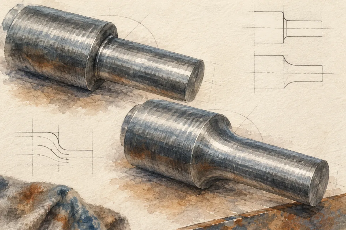
At shoulders or grooves where the section changes abruptly, the corner radius is an important dimension describing the geometry. Even apparently similar overall sizes may require different stress concentration references when radii and section ratios differ. When considering a design change that increases a radius, also examine mating components, machining allowances, and the overall load path. Avoid concluding that changing one dimension solves every situation.
If the drawing does not specify a radius, distinguish a value arbitrarily estimated from a photograph from an actual measurement. If the required reference uses the radius and the ratio of two diameters, organize all of them with consistent units and definitions. This article does not provide corner-factor tables for a specific geometry. Nor does it substitute a circular-hole solution for a corner factor.
Changing the loading direction makes the same geometry a different problem
Tension, bending, and torsion involve different conditions for determining the stress distribution even when a plate has the same hole. Mark not only the force magnitude but also its position and direction. MathWorks' example explicitly states its scope as a plane-stress model of a thin plate. Do not assume that components of different thicknesses or constraints follow the same model.
Repeated loads or loads acting in several directions also require consideration of their time histories and combinations. An illustrative static tensile value cannot replace a fatigue-life assessment under repeated loading. When looking for references, add loading terms such as tension or bending and the applicable assumptions to the geometry name “circular hole.” This reduces confusion between factors for different conditions.
Read an analysis maximum together with its location and model
In a separate numerical-analysis task, record the loads, constraints, material model, element size, and result component. Without the location and type of stress read, the maximum number in a color legend is insufficient for comparing analyses. In particular, ideally sharp corners or locations with concentrated loads or constraints may require additional consideration when interpreting results.
No actual finite-element analysis was run for this article, and it presents neither a validated mesh nor a stress-distribution image. To evaluate a new analysis, one can check the units, compare nominal values amenable to hand calculation and reaction forces, and then examine local distributions. Record what was verified at each stage. Do not claim that actual failure behavior was validated merely because an analysis screen exists.
| Review question | Required record | Confusion caused by omission |
| What is the load? | Tension, bending, or torsion; magnitude and position | Applying the same force number to different conditions |
| What is the geometry? | Width, thickness, diameter, radius, and hole spacing | Choosing the same factor based only on the hole type |
| What section is used in the denominator? | Gross or net section | Mismatch between the factor and nominal-stress reference |
| Which stress component is involved? | Circumferential, axial, or another component, and its location | Comparing different result values |
| Is the elastic assumption valid? | Material model and deformation range | Explaining local plasticity using elastic equations alone |
| Was life assessed? | Load history, assessment method, and material evidence | Reading a static stress value as fatigue life |
Explain material strength and geometric effects separately
It is tempting to think that a stronger material eliminates every geometric problem, but material properties and geometry-dependent local stress distributions are separate information. If the material model changes, check the analysis assumptions as well; requirements concerning fatigue, deformation, joining, and machinability also vary with the design objective. When explaining stress concentration, first state how the geometry creates its load path.
Do not interchange Kt, which describes geometric effects, with symbols such as the stress intensity factor used in crack assessment. Similar names can have different definitions, units, and applicable problems. This article focuses on the denominator definition of the elastic stress concentration factor; it does not calculate crack growth or fatigue notch factors.
Working notes to record before the factor
Include the component dimensions, loads and constraints, units, nominal-stress definition, and conditions of the factor reference in the final record. Also note, line by line, the differences between the idealized assumptions and the real component. If you save only one number, later it can be difficult to recover whether the gross-section basis was used or what the loading direction was.
The hypothetical factor-of-three circular-hole example is a starting point for understanding stress concentration. An actual design assessment requires references matching the component's conditions and any additional evaluations needed. These calculations do not claim that measurement, experiments, or analysis were performed; the official circular-hole solution is distinguished from separately prepared arithmetic examples.
Official sources and verification scope
- MIT OCW — Kirsch elastic solution for a circular hole
- MathWorks — Stress concentration example for a plate with a circular hole
Official references checked: 2026-10-08. Recheck on publication: assumptions and stress components of the circular-hole solution, and finite-width effects. No actual design assessment, analysis, or fatigue-life calculation was performed.
AI writing assistance. The examples, figures, and working records in this article are original illustrative examples. They are not presented as experiences or measurements from an actual user environment.
Original illustrations created to help explain this article.
Original on Tistory ↗